by Jim DeLoach, WU0I
Look for my latest antenna article, the 'Rhombic Loop Twofer', in the June 2017 issue of QST!
The Rhombic Loop Twofer is two antennas in one -- a small but potent rhombic by day, and a Loop Skywave by night. The 'mode' of operation is a function of whether the wires at the apex are connected or disconnected:
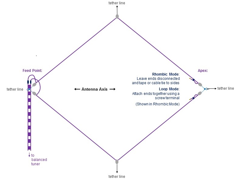
Full construction details, and a detailed theory of operation, are in the June 2017 QST!
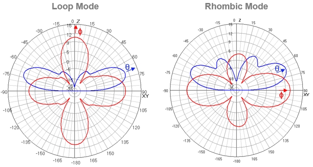
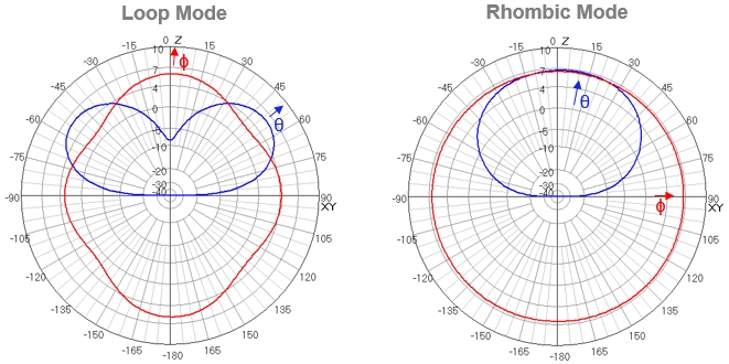
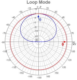
I used 4NEC2 -- a feature-rich yet remarkably user friendly antenna modeling tool -- to predict this antenna's radiation pattern. Below I show Rhombic Loop Twofer model results for each band for both 'rhombic mode' (apex corner not connected) and 'loop mode' (apex corner connected) and I compare and contrast the two patterns. Antenna patterns are inherently three dimensional, but they are usually plotted in two 'slices':
I annotate θ (Theta) and φ (Phi) on the plots. Graph units are in dBi -- gain relative to an isotropic radiator. The PSK31 frequency was used for each band. Modeling parameters reflect my California Coastal Mountains Field Day QTH and construction materials used: height above ground = 14 meters, 'Real ground' of type 'Mountainous Hills < 1000 meters', 18 gauge wire, no wire loading.
On 20 meters, rhombic mode takeoff angle can vary widely with height, as vertical sidelobes combine and separate. This height (14m) has a good single, relatively-low vertical lobe. 20 meter loop mode takes on a cloverleaf pattern, with a strong complementary perpendicular component. Takeoff angle actually decreases slightly relative to rhombic mode.

20 meter rhombic mode NEC file.
Curiously, rhombic mode behavior is completely different on 40 meters, where the antenna radiates straight up -- good for daytime contacts. In contrast, 40 meter loop mode takeoff angle is lower than and complementary to rhombic mode, good for longer, medium-range nighttime contacts.
40 meter rhombic mode NEC file.
On 80 meters, loop mode radiates up, and is essentially a 'Loop Skywave' Near vertical incidence skywave (NVIS) antenna, which perform very well for regional coverage. Radiation pattern characteristics as a function of height are relatively stable in loop node. Note that rhombic mode is not particularly useful on 80 meters.
In rhombic mode, gain increases, beamwidth decreases, and takeoff angle decreases as frequency increases and leg lengths are longer with respect to wavelength. 15 meters is probably the sweet spot for rhombic mode. Gain is substantial, the vertical takeoff angle is ideal for transcontinental 3,000 to 4,000 km paths, and the main vertical lobe has not yet fragmented (which it begins to do for bands above 15 meters). Note that loop mode is not useful on 15 meters.
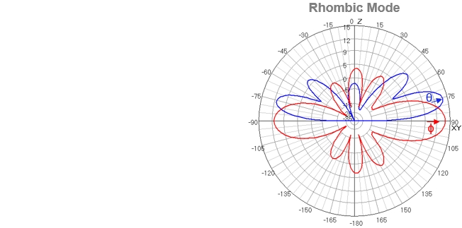
15 meter rhombic mode NEC file.
10 meter rhombic mode gain increases, horizontal and vertical main lobes narrow, but do not yet fragment, so performance remains quite strong. Takeoff angle lowers, so the antenna is more optimal for more distant transcontinental paths, and horizontal gain is now narrow enough to be be focused on a limited target area.
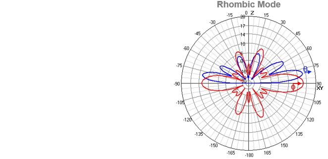
10 meter rhombic mode NEC file.
At 6 meters, the rhombic mode horizontal main lobe fragments in to three, but gain is still quite useful. Likewise, vertical lobes are also fragmented, but the main lobe is quite low and quite useful. At 6 meters, the opening angle is now to too big for leg length, relative to wavelength, to prevent fragmentation, yet the antenna remains useful. For this antenna, 6 meters is a bonus -- not entirely optimal yet still valuable.
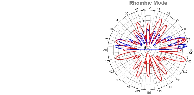
6 meter rhombic mode NEC file.
Rhombic Loop Twofer modeling plots in.pdf format.
My thanks to Jon Griffiths, W6PI, for his expert advice designing and modeling this antenna!
So you want to build a Rhombic Loop Twofer for Field Day; where should you point it?? Check out my web page Point Your Field Day Antenna!
(c) Jim DeLoach, WU0I, 2017.